5 Applications of JFET Transistors
The Current Regulator Diode is a JFET with the Gate tied to the Source and operating in the saturation region of the characteristic curve as seen in Figure 1.
In the saturation region, the current output is very constant over a wide range of Supply Voltages. With the Drain Voltage well-centered in the saturation region, noise on the voltage source will not cause changes in the regulated output current.
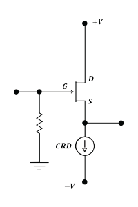
The CRD series of Current Regulator Diodes by InterFET have a unique feature; the Gate lead is brought out of the device and tied to the Source externally to increase the capabilities of the CRD. With the Gate lead on a separate pin from the Source, the device can be turned on and off like an analog switch. When a negative voltage is applied to the Gate lead V_{GS(OFF)}, the current flowing through the device will go to zero.
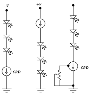
Another application for the Gate lead is to change the amount of current flowing through the device. In Figure 2, as the Gate Voltage V_{GS} goes more negative, the entire current output curve moves lower. This can be used to dim the LED output. The output change can be gradual or instantaneous with immediate stability.
The CRD will protect against surge currents as well as voltage fluctuations and because it is based on a JFET design, there is extremely low injected noise.
Another interesting characteristic of CRDs is that they can be biased to achieve near zero temperature-coefficient performance over a wide temperature range. As the temperature increases, the mobility of the majority carriers within the channel is inhibited, about 0.8\textsf{\%}/\textsf{\degree C}. Any reverse biased PN junction, in a CRD or bipolar Diode, exhibits a barrier-potential depletion width that decreases with increased temperature, at about -2.2\textsf{mV} / \textsf{\degree C}.
In addition to applications with varying temperatures, the CRD is also very well suited for demanding temperature extremes. The CRD has also performed well in high radiation environments.
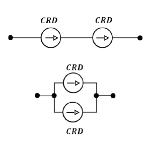
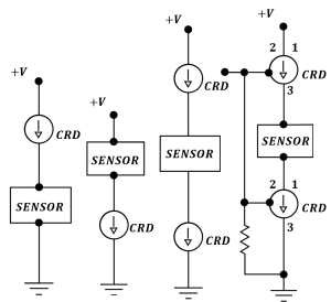
The Current Regulator Diodes (CRDs) will evenly split the load across multiple devices to increase the Voltage or Current carrying capability. By adding CRDs in series and parallel, both current carrying and breakdown voltage capability can be increased. (Figure 3).
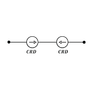
The current flow will be limited by the CRD in that direction while the CRD in the opposite direction will pass the current through (Figure 4).
The maximum number of LEDs is determined by adding the voltage drop across the LEDs and the CRD. Add the current requirements for each LED to select the correct CRD from the data sheet.
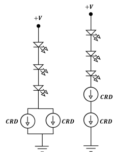
Driving LEDs that require higher current or higher voltage can be accomplished by stacking CRDs in series or parallel since they will share the load naturally by design.
By using a CRD to bias your sensors, it is possible to reduce the noise and increase the accuracy of your sensor, especially in a noisy electrical environment. The CRD will also act as an Analog Switch.
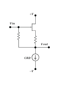
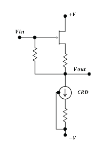
Transistor performance can be improved by the stable, well-defined DC bias point.
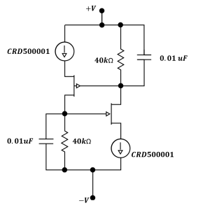
Cascode 200 \mu \textsf{\textbf{A}} Floating Current Source, Regulation \mathbf{(15 \textsf{\textbf{V}} \space – \space 30 \textsf{\textbf{V}}) \space \textsf{\textbf{is}} \space 0.00005\% / \textsf{\textbf{V}}}
This Cascode floating current source will regulate \bold{15}\textsf{\textbf{-}}\bold{30}\textsf{\textbf{V}} to \bold{0.00005\%/}\textsf{\textbf{V}} supplying \bold{200\mu}\textsf{\textbf{A}}. The output impedance will appear to be \bold{10} \space \textsf{\textbf{G}}\bold{\Omega}. The low voltage compliance is limited by the combination of the gate reference voltages to around \bold{8}\textsf{\textbf{V}}. The high voltage compliance is limited by the lower voltage rated JFET.